Special I/O Commands Intro[]
This chapter includes specialized input/output commands such as those for A/D conversions, generating audio tones, controlling LCD displays, stepper motors, servos, etc.
This chapter contains the following sections:
- Special I/O Commands
- ADin
- Button
- Count
- RCTime
- EnableHservo
- Hservo
- HservoWait
- GetHservo
- Servo
- Mservo
- Spmotor
Conventions Used in this Chapter[]
| { ... } | represent optional components in a command. The { } are not to be included. |
| [ ... ] | used for lists - the [ ] are required. |
| ( ... ) | used for some arguments. The ( ) are required. |
Important: Several of the commands described in this chapter specifically address hardware features of the microcontroller chip. Descriptions of these hardware features are beyond the scope of this manual.
Please refer to the H8/3664F or H8/3687F hardware manual, available at http://www.renesas.com for further details.
ADIN[]
Sets up the hardware A/D converter and stores the resulting value in a variable. The resolution is 10 bits.
Important: The ADIN command uses the microcontroller's built-in A/D hardware. A description of this hardware is beyond the scope of this manual. Please refer to the H8/3664F or H8/3687F hardware manual (see page 135).
Syntax
- adin pin,var
- pin is a constant or variable specifying the analog pin to use for the A/D input. Available pins are:
- AtomPro 24-M P0 - P3
- AtomPro 28-M P0 - P3 and P16 - P19
- var is a variable (word or long) that stores the returned value from the conversion (10 bit resolution).
Notes
The ADIN command converts an analog (0 - 5V) signal to a digital value from 0 - 1023. The input can be scaled by using a reference voltage (Vref).
Examples
volts var word
adin 1,volts
will convert an input voltage (0 - 5V) on pin 1 to a digital value of 0 - 1023 and store the result, right justified, in word variable "volts". The first 6 bits of "volts" will be zeros.
BUTTON[]
Processes a momentary switch contact, such as a button press. Includes debouncing and auto-repeat. The BUTTON command should be used in a program loop so that it is repeatedly accessed.
Note: Note that all timing (except debounce) for the BUTTON command is set by counting program loops, so some experimentation may be required to find the best values.
Syntax
- button pin, downstate, delay, rate, loopcounter, targetstate, target
- pin is a variable or constant the specifies the I/O pin to be used. Pin will be set to an input automatically.
- downstate is a variable or constant (value either 0 or 1) that specifies the logical state of the pin when the button is pressed. 0 = low, 1 = high. This lets you use normally open or normally closed buttons.
- delay is a byte variable or constant (0 - 255) that specifies the number of program loops to execute before first entering the auto-repeat sequence.
- If delay is set to 0 both debounce and auto-repeat are disabled.
- If delay is set to 255 debounce is enabled, but autorepeat is disabled.
- rate is a byte variable or constant (0 - 255) that specifies the number of program loops to execute before auto-repeating, after the initial delay has expired.
- loopcounter is a byte variable used to store the current number of program loops. This variable must not be used for any other purpose within this program loop. If more than one BUTTON command is used in your loop, you must specify a different loopcount variable for each.
- targetstate is a variable or constant (0 or 1) that determines the logical state of the button for a branch to target to occur. 0 = not pressed, 1 = pressed. (Pressed and not-pressed are defined by downstate.)
- target is a label to which execution will branch if the button is in targetstate and debounce, delay and rate conditions are met.
Notes
BUTTON checks the state of an I/O pin connected to a switch and branches according to the result. BUTTON is actually just a form of conditional branch; it does not produce any numeric result or save any values.
For the following notes, assume that the BUTTON parameters have been set to see a LOW state as downstate and to branch when the button is pressed (down). BUTTON is executed within a loop.
- Not pressed. If the button is not pressed, loopcounter is reset and control simply passes to the next program statement. After the following statements are executed, control must be returned to the start of the loop.
- First press. If the button is pressed for the first time (i.e. the previous loop pass showed it as not pressed), BUTTON first does a debounce check.
- If debounce fails (i.e. the button wasn't actually pressed), control passes to the next program statement as above.
- If debounce passes (i.e. the button is really pressed) BUTTON branches to the statement defined by target. Loopcounter is also incremented for use by the auto repeat function. The sequence of commands following target must return to the start of the loop.
- Repeat delay. If the button is still pressed the next time BUTTON is encountered (i.e. on the next pass through the loop), loopcounter is again incremented. If loopcounter has reached the value specified by delay execution will branch to target and loopcounter will be reset. If loopcounter has not reached this value, it will be incremented and execution will continue with the
following program statement.
- Auto-repeat. If the repeat delay has expired, the sequence of steps under "Repeat delay" will be executed, but using the rate value for loopcounter, rather than the delay value. This lets you
set the initial delay and the repeat rate independently.
Debouncing
Mechanical buttons often close and reopen many times (sometimes hundreds of times) before stabilizing in the pressed position. This is because of mechanical vibration of the components of the button. To avoid having BUTTON see these intermittent cycles as many button presses, it has a built-in debounce feature.
When BUTTON sees a valid downstate for the first time, it delays approximately 20 ms and checks again. If the downstate is still valid, it assumes that the button is really pressed and continues processing. If downstate is no longer valid, this could be the result of a bounce so it is ignored and control passes to the next program statement.
If the button really was pressed, the next execution of the BUTTON command will show a valid downstate and processing will continue as above.
Examples
delay var byte
rate var byte
count1 var byte
count2 var byte
delay=80
rate=40
startloop
   button P4,0,delay,rate,count1,1,right
   button P5,0,delay,rate,count2,1,left
goto startloop
right
   ;code to rotate to the right
goto startloop
left
   ;code to rotate to the left
goto startloop
This program will check two buttons, one for right on pin 4, the other for left on pin 5. The buttons are normally open, closed when pressed, so they pull the pins LOW when pressed. Depending on which button is pressed, a stepper motor (or other device) will be caused to turn left or right.
The two BUTTON commands use different loopcount variables, count1 and count2.
Note: This program does not include code to deal with simultaneous pressing of the two buttons.
COUNT[]
Counts the number of cycles (0 - 1 - 0) on an input pin during a specified time period. Used to determine frequency. The minimum pulse width that can be counted is 4 µs.
Syntax
- count pin,period,cycles
- pin is a variable or constant that specifies the input pin to be used. This pin is automatically set to input mode.
- period is a variable or constant that specifies the counting time in milliseconds.
- cycles is the variable in which the total count will be saved. Cycles must be large enough to store the highest expected number of cycles.
Examples
total var word
count p3,10,total
Will count the total number of 0-1-0 transitions on I/O pin 3 for 10 ms, and store the result in "total". For instance, if the input frequency was 50 kHz, the count would be 500 (± 1 count).
RCTIME[]
Measures short time intervals, such as the charge/discharge time of an R/C circuit.
Syntax
- rctime pin,state,{timeoutlabel,timeout,}result
- pin is a variable or constant that specifies the I/O pin to use. This pin will be placed into input mode and left in that mode when the instruction finishes.
- state is a variable or constant (1 or 0) that specifies the state which will end the timing period.
- TimeoutLabel is a program label. If the command times out before the pin state changes, execution will continue at this label. The default timeout is 65535 µs. If no TimeoutLabel is specified, program execution will continue with the next statement in the event of a timeout.
- Timeout is a 32 bit value that specifies the timeout in 0.5 µs units.
- ResultVariable is a variable in which the time measurement, in µs, will be stored. This variable must be large enough to store the maximum value set by TimeoutMultiplier.
Notes
Warning: For those users who are converting code from a Basic Stamp to run on the Basic Atom Pro, The semantics of the state parameter is different.
RCTIME can be used to measure the value of capacitors or resistors, as well as to make other triggered timing measurements. One common use is to measure a potentiometer setting.
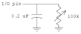
Figure 20 - Measuring time with RCTIME
With a circuit similar to that shown in Figure 20 the RCTIME command is used as follows:
- Set the I/O pin to be an output and set it high.
- Wait long enough for the capacitor to fully charge. About 5 time constants (i.e. 5 x R x C) will do nicely. (The "time constant" of an R/C circuit is the time for it to charge to 63.2% of the applied voltage, or to discharge to 36.8% of the initial voltage. It is calculated using the equation T = R * C where R is in ohms and C is in farads.)
- Issue the RCTime command, which will switch the pin to an input and "watch" the voltage as the capacitor discharges through the variable resistor.
From the resulting time, the resistor or capacitor value can be calculated (you have to know at least one of them accurately if absolute, rather than relative, results are required).
To help in your calculations, here's some information about the BasicATOM Pro's I/O pins:
| Approximate voltage to switch from low to high state on a rising input | 2.05V |
| Approximate voltage to switch from high to low state on a falling input | 0.80V |
It takes about 1.83T (where T is the time constant) for the circuit to discharge enough to trigger the RCTime command. This means that the time constant = ResultVariable / 1.83. A sample calculation is shown below under Examples.
Note: It's very convenient that the time constant equation also works perfectly if time is in µs and capacitance is in µF.
Examples
This program assumes that the circuit shown in Figure 20 is used, with the variable resistor set to about the mid point of its rotation. Some scaling is done to allow integer arithmetic to be used.
dtime var word
resist var word
high P3
pause 10 ; wait for capacitor to charge
rctime P3,0,dtime
resist = (10000*dtime)/(183*2) ; see text below
The program sets P3 to output, high state, and then waits 10 ms for the capacitor to charge fully. The RCTIME command then changes P3 to an input and waits for a low state, which occurs when the capacitor discharges to about 0.8V. The time, in microseconds, is stored in dtime.
The resistance is then calculated using the formula:
- resistance = dtime/(1.83 * capacitance)
However, to accommodate the integer arithmetic, the 1.83 and capacitance are each multiplied by 100 (giving 183 and 2, respectively), so the numerator must be multiplied by 10000 to compensate. These steps could be avoided by using floating point calculations, if desired, at the expense of program complexity and calculating time.
In the example, if dtime is 1830, the value of the resistance comes out to be 50000 ohms.
Important: In most cases an absolute value won't be needed, only a relative position of the variable resistor, so the resistance calculation can be simplified.
ENABLEHSERVO[]
Enables the hardware servo control system and specifies its parameters of operation.
Syntax
- ENABLEHSERVO
Notes
ENABLEHSERVO is a compile time directive that tells the compiler to add support for the hardware servo control system. The HSERVO system uses the TimerW (or TimerZ0 in ATOM-Pro Plus) to produce interrupt driven signals for up to 32 servos.
ENABLEHSERVO has no arguments.
HSERVO[]
Sets the position and speed of up to 32 servos. Before using this command the ENABLEHSERVO compile time directive must be included in your program.
Syntax
- HSERVO [Pin\Pos\Spd....PinN\PosN\SpdN]
- Pin...PinN are expressions that specify the pin numbers connected to the servos whose position and speed are to be set.
- Pos...PosN are expressions that specify the desired positions for each of the specified servos (range -12000 to +12000).
- Spd...SpdN are optional expressions that specify the speed used to move each servo to its new position (default 255).
Notes
The HSERVO command is a background timer interrupt driven command. It allows you to set the new position and speed to move to that position of up to 32 servos at one time. Each servo set will start moving to its new position imediately after the HSERVO comand finishes.
To deactivate a servo that has been used set its Pos to -16000.
Example
HSERVO P1\2000\100,P2\-1000\100
HSERVOWAIT[]
Waits for specified servos to reach position before continuing.
Syntax
- HSERVOWAIT [pin#,pin#,...]
- Pin# is an expression that specifies the I/O pin number to which the servo is connected.
Notes
HSERVOWAIT pauses program execution until the specified servos have reached the postions set by the HSERVO instruction.
GETHSERVO[]
Get the current position of the specified servo. Optionally determine whether the servo is idle or not.
Syntax
- GETHSERVO pin,position{,idle}
- Pin is an expression that specifies the I/O pin number on which to check servo position.
- Position is a variable where GETHSERVO will store the current position (-12000 to +12000, center = 0) of the specified servo. (Most servos will not reach the maximum values shown.)
- Idle is an optional variable where GETHSERVO will store the current state of the servo. A value of $FFFFFFFF means the servo is idle (at its final position).
Notes
Gethservo is used to determine the current position of a servo and whether it has finished moving to its final position.
Example
getservo p0,pos
or
getservo p0,pos,idle
If the servo is at its new position "idle" will be a non-zero number. If the servo is still moving to its new position then "idle" will equal 0.
SERVO[]
Operates a servo motor.
Syntax
- servo pin, rotation{, repeat}
- pin is a variable or constant that specifies the I/O pin used to control the servo.
- rotation is a variable or constant that specifies the position to which you want the servo to rotate. The value of rotation should fall within the limits of -2400 to +2400*, with 0 being the center position. See the Notes below for a discussion of servo motors.
Important: *Exceeding these values could damage your servo.
- repeat is an optional variable or constant that specifies the number internal cycles the command runs (default = 20). This value must be high enough for the motor to reach the desired position, so higher values may be required for larger angles. Repeat allows the servo to reach the desired position before
the program continues and perhaps sets a new position.
Notes
Servo motors are controlled by a pulse width modulated signal that is applied repeatedly at 20 ms intervals as long as the motor remains under control. The pulse width varies from 0 to 3 ms (this is standard for servo motors). Values from 0 to 1.5 ms rotate the motor to the left, values from 1.5 to 3.0 ms rotate it to the right. A pulse width of 1.5 ms sets the motor to the center of its rotation. These values are set by adjusting the rotation parameter (see above). (Values of -1200 to +1200 don't actually cover the full 0 to 3 ms pulse width range. They are restrained at both ends to prevent over-rotation of the servo, which could cause damage.)
The amount of rotation varies with different motors, from about 90 degrees to 270 degrees total. You may have to determine this amount by experiment if you don't have access to data sheets.
The control signal must be continuously applied or the motor will drift from its set position (i.e. it won't generate any torque with no signal). This implies that the SERVO command should be used in a program loop.
Since servo motors take time to reach the set position, the SERVO command repeats the pulse output for a sufficient time. Depending on the individual servo motor, and the amount of rotation change required, you may have to adjust the repeat parameter for the command.
For reference, the following wire colors are used by different manufacturers:
| Manufacturer | Power (+5V) | GND (Vss) | Control |
|---|---|---|---|
| Airtronics | red | black | brown |
| Futaba J | red | black | white |
| KO Propo | red | black | blue |
| Kyosho/Pulsar | red | black | yellow |
| Japan Radio (JR) | red | brown | orange |
Examples
pos var word
setpos
   ;code to determine desired position
   servo P4,pos,50
goto setpos
This simple program controls a servo connected to P4. The desired position may be determined by any number of different input factors, depending on the application. Since the 20 ms control sequence is repeated 50 times, the position may only be changed about once per second.
MSERVO[]
Operates multiple servo motors. Similar to SERVO.
Syntax
- MSERVO pin,
- servo1{\servo2{\servo3{\servo4{\servo5{\servo6{\servo7{\servo8{\servo9{\servo10{\servo11{\servo12}}}}}}}}}}}{, repeat}
- Pin is an expression that specifies the pin number controlling servo1. All other servos are controlled by the next pin (i.e. servo2, pin+1, servo3, pin+2 etc...)
- Servo# is an expression that specifies the position to which you want the servo to rotate. A value from -2400 to +2400* is used with 0 being center. The maximum +2400 and minimum -2400 will vary based on the servo being used.
Important: *Exceeding these values could damage your servo.
- Repeat (optional) Specifies the number of internal cycles the command runs (defaults to 20).
Notes
The MSERVO command is similar to the SERVO command except that it operates more than one servo motor. MSERVO is a foreground task.
Note: See the SERVO command (page 160) for more detail on MSERVO parameters and the operation of servo motors.
Example
MServo p0,0,-1000,1000
Assumes three servos are attached to P0,P1 and P2. The pin argument specifies the first pin used.
SPMOTOR[]
Operates a stepper motor.
Syntax
- spmotor pin,delay,step
- pin is a variable or constant specifying the lowest numbered of 4 output pins used. For example, if pin = P0, pins 0, 1, 2 and 3 will be used.
- delay is a variable or constant (0 - 65535) that specifies the delay in milliseconds between steps. The delay controls the speed at which the stepper motor operates.
- step is a variable or constant (-32682 to +32682) that specifies the number and direction of steps the stepper motor will execute. With correct wiring, positive values are clockwise, negative values are counterclockwise.
Notes
Stepper motors are precision devices that are used to control position or rotation in small increments. Each step moves the motor an absolute, predetermined amount (the amount varies with different stepper motors and may be determined by experiment, or by referring to the manufacturer's data sheets). Stepper motors are commonly found in XY positioning tables, graphing devices, disk drives, laser printers, etc.
Stepper motors may be unipolar or bipolar. Bipolar motors require slightly more complex control circuitry. Typically, unipolar steppers have 4 wires, bipolar have 5 wires.
Note: The SPMOTOR command supports both unipolar and bipolar stepper motors. Wiring for bipolar motors is not described in this manual.
Since the inductive load of a stepper motor may exceed the ratings of the BasicATOM Pro, it should be driven using a buffer amplifier. The most common device for this purpose is the ULN2803A Darlington array, which includes protective diodes for inductive loads.
A sample circuit using a ULN2803A is shown below. Further circuit design and determining the correct wiring of the stepper motor are beyond the scope of this manual. Experimenting to find the right connections is a bit tedious, but you won't damage the motor by doing so.
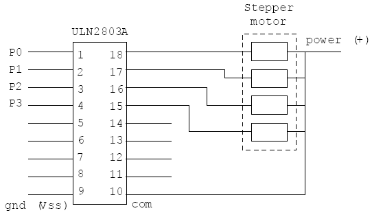
Note: Data sheets and application notes for the ULN2803A are available on the internet: a quick search will let you find many resources.
Examples
delay var word
step var sword
delay = 50
step = -60
spmotor P0, delay, step
will cause the stepper motor to make 60 counterclockwise steps at intervals of 50 ms.